| Modifying
the RandMcNally Streetfinder GPS ________________________________________________________________________________________________________ |
||
|
|
ecently I bought a second hand PalmVx with the intention to use it with a GPS in the car. Altough I had an old Motorola Oncore 8-channel OEM module and wanted to connect this to the Palm, I actually was offered a Rand McNally Streetfinder Palm Companion as well. This device looked promising since it came with a windshield mounting bracket and power cord for the cigaret lighter. As handheld outside the car it runs on batteries. |
|
|
The Palm Vx is operating from a 4.1 Volt Lithium cell. This power is available at the 10-pin connector that is used to connect to the Streetfinder GPS. The thing with Lithium cells is that they must not be overcharged. A usual NC or NMHI charger setup could be to keep the cells constantly trickle charged. Not so with Lithium cells. Ideally they are charged "Constant Voltage, current limited". This means the external voltage should never exceed the targeted cell voltage, and also not provide too much current. Initially I started thinking about a proper circuit that would meet all Lithium cell charging requirements, but this lead to a number of components that probably would probably not fit anymore in the existing housing of the Streetfinder GPS. Then I decided to examine the Palm Cradle charger. With varying load the cradle delivered more current when the load was higher. This definately did not look like a constant current source. Actually it looked more like a voltage regulator with about 1 ohm internal resistance (see cradle test). This also means that if you leave your Palm powered on in the cradle it will never get fully charged, especially if you keep the backlit on. Now I thought, what is good enough for the cradle might be good enough for my Streetfinder charging circuit. Thus my circuit essentially became a 4.04V voltage regulator with input an resistor limiting the current. What I added was a logic-level mosfet to prevent the palm from discharging when the board power is not available. The whole circuit should be possible to build for 2 to 3 Euro. SMD components are not necessary.
|
|
|||
|
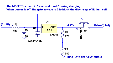
The circuit The circuit I used is based on the LM317L adjustable regulator. The 4.04V output level is pretty critical, therefore you will have to tune the value of R2 to get the level that your charger also provides. I just tried a few combinations of series/parallel resistors until I got the right value. The potentiometers I had were simply too big for the small space available for the circuit. Note that the LM317 needs a minimum load to operate properly. If you use the LM317L (TO92) instead of the LM317T (TO220, which is too big anyway) you may increase the R3/R2 values to maximum twice as high.
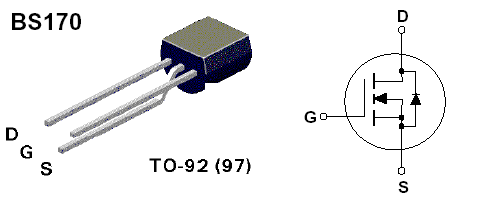
R1, C1 and the D1(18V zener or 15V surge surpressor) provide some filtering of electrical noise always present in a car. Without it the maximum Gs value of the fet (20V) might get exceeded. Make sure that the voltage rating of C1 is at least 25V (a tanalum cap is perfect). If you are really crammed for space you may even leave C1 out. R1 also serves to as a current limiter. Therefore the power dissipation of the LM317L is quite low. Note that R1 should be a 1/2W type. I did put 3 resistors of 33 ohm that I had in series. Prevent any output shorting longer than a few seconds to prevent R1 from getting too warm. The BS170 fet provides protection against discharging the Palm battery when the power cord is not plugged in. Note that normally this logic-level fet is used with current flowing from drain to source. Here it is used in a different configuration because of the built-in protection diode (see image below) that would ruin the goal of preventing the discharge.
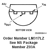
Primarily R1 limits the current to the lithium cells. However when the cell is getting full the output resistance will determine the charge current. The lithium cell has about 1 ohm and the fet adds about 1 to 3 ohm. A nice side-effect is that the gate voltage increases at lower currents, so the fet is more saturated (lower Rds-on) when the cell reaches full charge. Below you find the pinout of the LM317L:
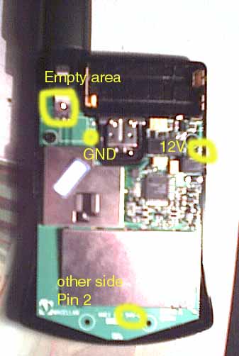
Making it Fit The only reasonable bit of space I could find was the area just below the antenna. This allows a small piece of circuit board (3 holes wide, 8 holes long). The antenna leads are flat metal sheets that will lay underneath the circuit. Make sure you isolate the two with a piece of plastic or paper!
The result With the Palm powered off the charge current will be 40 to 50mA with 12V to 14V connected on the power cord (see details). This is with a cell filled at 3.85V. With the Palm operating (similar as with operating the Palm on a cradle) the cell voltage will eventually reach a certain level that is below the maximum charge. Running Cetus on the Palm with the Streetfinder on board power, the balance is reached at a cell voltage of 4.00V. I still have to run the test with backlit on and running other programs. With the Palm powered off the cell will eventually reach maximum level for your Palm. (However you better not leave it unattended in the car if you live in a big city as I do...) Last updated: June 14, 2003 |
||||


