| Experiments
with the LM2575 ________________________________________________________________________________________________________ |
||
|
|
ormally I use linear voltage regulators like the 7805 or LM317. These are simple to use and work great but can dissipate quite some heat if powered from a higher voltage like a 12V board accu and delivering 0.5 to 1.0A at 5V. Cooling is then definately required. Heat also means battery power is waisted. An alternative is to use a switching regulator. Voti provides affordable versions of the (not so modern anymore) LM2575T-5.0. This is a fixed 5V version. The documentation from National Semiconductor is pretty detailed. I will not repeat is here. Instead this page describes my experiments with the LM2575. Last updated: March 7, 2004 |
|
|
Circuits tested First I tried the textbook examples from the NS documentation. This was done with components I had at hand. This covered a number of components, including a small inductor of 20mH, a 2 x 1.1mH toroid coil, a bare toroid core, 1n4148 diodes, later a schottky diode and several capacitor values. The standard buck regulator circuit delivers a +5V output. This is a rather straightforward circuit and will operate with a wide spread of component values. Optimal values should be selected however to get minimal ripple, minimal noise to the power source, maximum efficiency etc. Note that the quiesent current is about 10 to 14mA. The buck-boost regulator circuit delivers -5V output. I hoped this would a nice way to generate a negative voltage for e.g. an LCD-display. However this circuit requires component values that are similar to the buck regulator at high load. Probably because the LM2575 as buck-boost regulator tries to bootstrap its own operating power. Together the need for subtantial bigger output capacitors I abandoned the idea of using the LM2575 in buck-boost for an negative LCD voltage. There is an alternative further down on this page. The inductor The inductor needs
to be selected corresponding the load current. With an input of 12V
and a low load (tried <10mA) the LM2575 works with a small 20mH/60ohm
inductor (also available at Voti). For higher loads lower inductor values
are needed (order of magnitude 330uH). The inductor value also depends
on the input voltage. The documentation shows graphs that help to determine
the right value. Just make sure that you find one that van handle the
load. Common 'resistor package' style inductors have too high series
resistance and are not usable. Also make sure that the core does not
saturate at the operating current. The diode Initially I did not have acces to a schottky diode. This is the preferred type of diode since it is fast and has a low forward voltage drop, thus increasing overall efficiency. Instead I started with a couple of 1n4148 diodes in parallel. This works fine since it is a fast diode. The forward drop can be 0.9V at 100mA. If you have diodes with similar characteristics (from the same batch?) it is ok to parallel them. The maximum current is 200mA for a 1n4148, I used 2 in parallel to test a 200mA load. Note that the diode spec should be at least 1.2 times the output load. If you want to withstand continues short circuit, the diode must be able to handle the limit of the LM2575 which is over 1A. Then use a bigger diode. E.g. the SB350 (3A) or SB530 (5A) family. The latter should be normally available at Conrad. The capacitors The documentation
states these should have a low ESR rating. It is difficult to find the
actual ESR value specified at companies like Conrad. At least take ones
that are referred to as low ESR. A higher voltage capacitor then strickly
needed is said to have lower ESR values. It also seems to increase the
life-time of the capacitor. Efficiency The power efficiency
of the cicuit depends on number of factors. A good inductor helps, but
primarily the diode is important. With a pair of 1n4148 in parallel
and a load of 200mA I measured 71% efficiency. With a proper Schottky
diode this became 75% and went up to 79% increasing the load to about
400mA. These values are not extremely good for a switching regulator
nowadays, but they do allow operating without a (big) heatsink for the
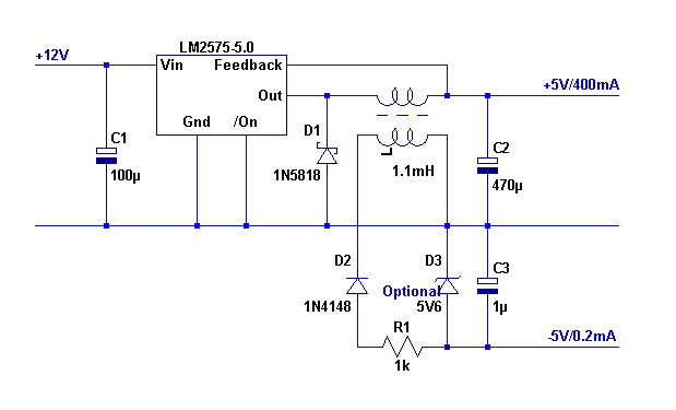
regulator. Buck regulator with additional negative voltage
The
above circuit shows a way to generate a second voltage. The toroid coil
at hand had 2 sets of windings. So I tried to see if I could get some
power from it. This works great as long as there is at least some current
drawn on the main output (a few mA is enough). The coil then acts as
a sort of transformer. In the above circuit the out-pin of the LM2575
switches between about -0.5 and 11V. Since the circuit output is 5V
the 'transformer' is driven by a about 5.5V (top) AC voltage. This is
also available on the second winding and after rectification gives about
5V. The 5.6V zener was not needed in my case since it was meant for
a graphics LCD that works between -5 and -8V. Actually the zener lowered
the output voltage just a bit too much and I left it out.
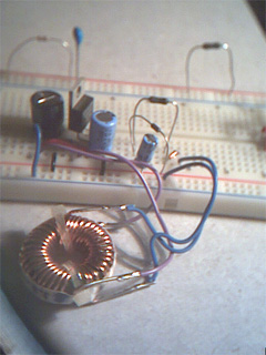
The image above shows not a lot of components are needed. The biggest component I used is the coil. It would be nice to test some smaller versions, but I could not lay my hands on the right ones. Other output voltages (>5V) The LM2575 is available
in several version with different output voltages. The documentation
mentions only differences in resistor values in the feedback circuit
internal to the LM2575. I tried to add a series resistor to the feeback
pin to see if I could change the output voltage. This works like a charm.
With a 10k potmeter in series I could control the output between 5V
to over 10V using a 12V input. The formula for the output voltage is: |
||
|
The result The LM2575-5.0 is a simple
regulator to use. The additional components around it (schottky, low
ESR caps, toroid) need some attention for optimal operation. Perhaps
the only non-common part is the inductor, which might require some searching
in the market. You can make your own if you find a bare core with known
Al. The output can be a bit noisy at higher loads (<200mV). Then a L/C filter as usually is found in switching power supplies will help (reducing ripple by a factor 10). Also you might want to consider a linear regulator as follower for even better results. The output voltage can be higher than 5V with the use of a feedback series resistor. This should even be possible in a e.g. a 1.2 to 25V power supply with a LM317 follower circuit. Since the efficiency is relatively high a small heatsink or none at all will do. The remaining loss (about 20%) will be dissipated by the LM2575, the diode and probably a fraction by the capacitors. So the 20% will not all go to the regulator itself. Last updated: March 7, 2004 |
||

