| Interfacing
the I2C Graphics LCD with a microcontroller ________________________________________________________________________________________________________ |
||
|
|
egularly one wants to enhance a small microcontroller project with an LCD display. When you want to display a bit more text than fits on a 2*16 character LCD there is a choice to go for an 4*16 or 4*24 LCD but these are getting bigger in size and also more expensive. Some time ago I ran into an affordable small graphics LCD, similar as those used in mobile phones. Documentation was difficult to find, so I noted down my experience in this page. |
|
|
The display
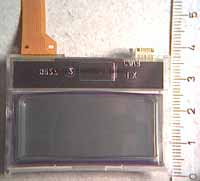
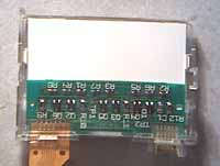
The LCD display I found was the LPH7653 made by Philips. It's specifications are:
The connector
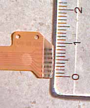
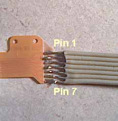
The display is equipped with a very flexible foil cable. It might be possible to remove this from the LCD by cutting out a piece of the plastic housing to reach the soldering. However the connector on this cable has a spacing of about 1.27 mm, so instead I chose to try and solder it to a stripped standard 1.27 mm flatcable. This is a bit of precision work but not undoable. The foil cable does not quickly melt, just as I hoped. Just make sure not to use too much solder. The pinout
The protocol The communication to the LCD uses the I2C interface. There are only 2 wires is involved: a clock and a data signal. More information on I2C can be obtained here. The sequence of events to the LCD is as follows: Send an i2c start
condition The image is addressed
as 4+1 rows by 97 columns. Per row the image is addressed from left
to right. Each byte corresponds with a vertical set of 8 pixels, with
the least siginificant bit at the top. The 5th row only visualizes the
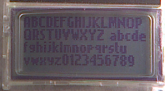
lowest 3 bits (height 4*8+3=35). After any byte the communication can be stopped by sending an i2c stop condition. Thus each vertical row of 8 pixels may be written individually. The software This is a graphics LCD. The LCD does not store a character set. Therefore if you want to show characters, you will have to "draw" them yourself. I did some experiments with a 7x5 and 7x6 fixed characterset. These looked too "thin" to my taste. Finding a better font was quite difficult. Eventually I decided to use a proportional font similar as in use in mobile phones. I guess the mobile phone manufacturers do not use these without a reason. The font might not be perfect yet, e.g. I trimmed the 'M' and 'W' width to 6 pixels, but it suits my needs well enough. The readability is much better than the other fonts I tried. Source code for a 8051 in C can be found here. If you have another language (e.g. assembly) or processor family you probably need to convert it, but the code may help you understand how to program the LCD or work with fonts. The font is displayed below in the LCD.
|
|
||||||||||||||||||||||||||||||||||||||||||||||||
|
The circuit My
microcontroller circuit was powered by 5V. Together with the other voltages
that the LCD needs, this could make one think the circuit gets very
complex. However the situation is not so bad. The -8V e.g. does not
need a lot of current or be very stable. The backlit can also be powered
from 5V with a simple series resistor. And the 3V operating power for
the LCD can be derived with 2 small components. The above circuit
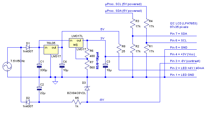
is what I actually used for testing. The I2C signal
levels are reduce using R3/R2 and R4/R1. Another processor then I used
(AT89S8252) might have other output levels, especially is there is a
much weaker internal pull-up.
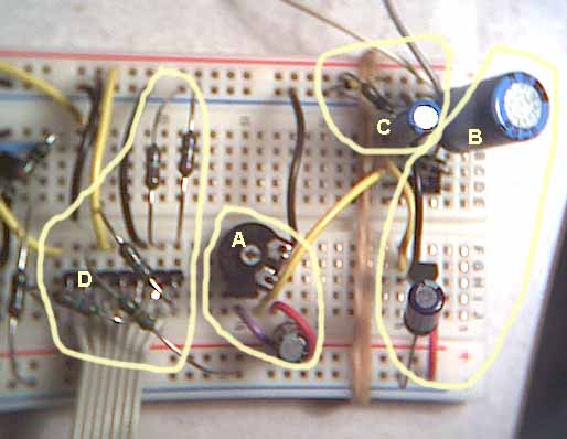
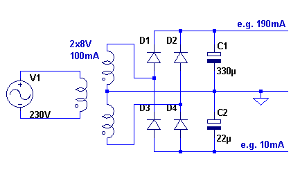
The image above shows the components for the 3V power (A), 5V power (B), -8V power (C) and the resistors for the level convertors and the backlit (D). Note that this is an example circuit. I found that powering both my microprocessor ciruit and the 40mA of the backlit was a bit too much for the 5V regulator (78L05). The output dropped 0.4V because it became too warm. You might be better of with a 7805 that can handle up to 1A (if you cool it enough). Also note it is normally not good practice to put a load on an AC adapter or transformer that is not symmetrical. One half of the AC cycle is used to provide power to most of the circuit and the other half of the AC cycle only to provide the -8V contrast voltage. If this balance is too far of, your adapter may get really warm. I did not notice it in this circuit, but have seen it in the past. A better rectifier circuit would be as shown below using a transformer with double windings. Here an inbalance will not cause trouble at all.
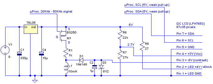
I also worked on
another circuit that only requires +5V and generates its own negative
voltage. It uses the microcontroller to provide a clock for a very simple
inverter circuit. The logic level pmos fet BS250 is driven by a clock
signal of about 40Khz. I generate this from a interrupt routine. The
fet allows a current to build up in the coil and abruptly stops it.
The coil forces the current to continue and the diode D1 starts to conduct
and thus builds up a negative voltage in C2. The zener determines the
value of the negative voltage (5 to 8 volt is fine). The +3V draws extremely little current. The circuit below therefore only uses R6/R7 to get about 2.7V from the 5V supply. The LCD seems to be happy with it. My microcontroller has weak internal pull-up's. I tried connecting them directly to the SCL/SDA of the LCD and see if there are static electricity protection diodes present that prevent too high input voltages. The lcd still works, the signal levels are max 4V. This is a bit higher then I expected, probably the protection overflows to the 4V of the LED's. Certainly not to the 3V, that would have shown a measurable increase. This circuit can be powered with a single voltage (9V battery e.g.). It is of course possible to combine elements of both circuits.
The result The LCD has a good contrast and is very readable when you use a bold/proportional font. The LED backlit is not extremely powerful but makes the LCD readable in the dark. When in normal light conditions it is already readable enough by itself. Providing power to the LCD takes some work, but is not too complex. The negative voltage for the contrast might make battery operation a bit more difficult though (perhaps you can also tap it from an MAX232). Connecting the foil cable is a bit tricky without a matching connecter, but it can be soldered. The missing support for characters requires more ROM space on the microcontroller (about 600 bytes depending on how many characters you really need). On the other hand it allows you more 'user defined' characters than the usual 8 found in a HD44780 character LCD. Total software control also allows images of course. All things considered it is a good LCD for projects where a normal character display is just too big, you do not have a lot of IO pins for an LCD, or where you need the graphics. Last updated: February 25, 2004 |
|||||||||||||||||||||||||||||||||||||||||||||||||
