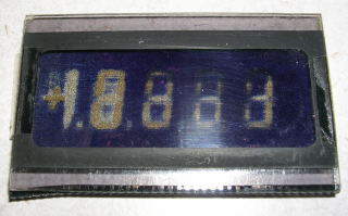
The
bad LCD display
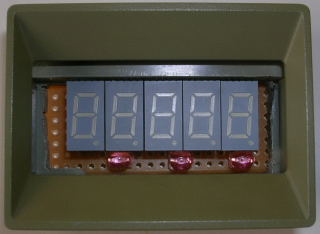
Replaced
it with 9mm LED displays and 3 LEDs
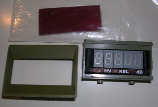
With
printed symbols on paper
Paper
is made more black with felt pen
Recently I was able to cheaply buy a second hand Fluke 8050A made in the early eighties. It is a nice 4.5 desktop digit meter, but a typical problem seems to be that the LCD wears out and goes black. Replacement LCD displays are hard to find, not cheap and probably lead to similar problems in due time.
The LCD display is interfaced by standard components (CD4054 and CD4056) that drive each segment individually. This allows it to be replaced with a LED 7-segment display. However LCD displays are driven normal/inverted about 30 times/second. LED displays can be used by disabling this clock and connect it to a fixed level (high).
Since my Fluke does not have the battery option I was pretty confident that the power supply would be able to provide the additional LED current. The LCD drivers are able to sink current per segment in the order of 2mA. Sinking capability is somewhat higher than sourcing, so I decided on an LED display with common anode.
Since I had no idea how bright a LED display is with this amount of current, I ordered the brightest 9mm displays I could find. If they turned out too bright I could always reduce the current. And that is what happened. In the end a series resistor of 2k2 showed proper results. With 1k the display was brighter, but some bleeding to neighbouring segments started to become noticable.
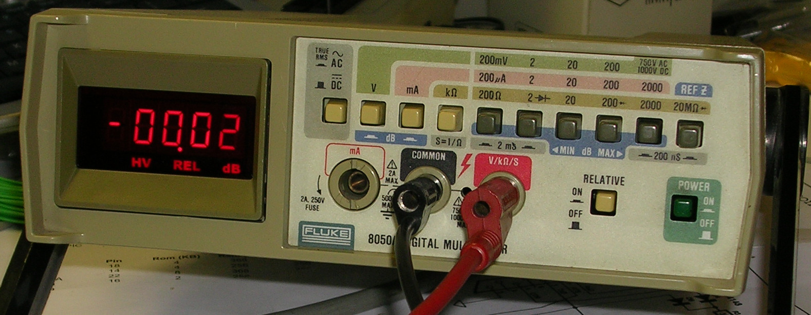
The LCD display also has a couple of special symbols for high-voltage(HV), low battery(BT), decibel (dB) and relative measurement (REL). Of course these have to be handled differently and I simply printed them as inverted text on paper. The paper is then lit from behind with separate high bright LEDs. I blackened the laserprinter output a bit more with a felt pen.
Another special case is the plus (+) and minus (-) of the LCD display. Personally I do not see the need for a plus symbol, so I decided to use the minus only since the LED can provide this nicely. The most significant digit segment g is used for this purpose. To “disconnect” it from the digit I tipped a small peace of the segment with a black CD felt pen.
However the behaviour of the +/- signals is a bit strange. I have no knowledge of how this worked originally on the Fluke. After playing around what seemed to work in all measuring modes (R/V/A/dB and REL combinations) is to use the inverted '-' signal and disable the segment when '+' is high (??!!). Without using the '+' signal, measuring ohms has the minus sign always on. Oh, well, this can all be done using a single small BS170 mosfet.
Below is shown the detailed images of the whole process, the circuit diagram of the display board and the circuit modifications.
The new LED displays in stages
|
|
|
|
|
|
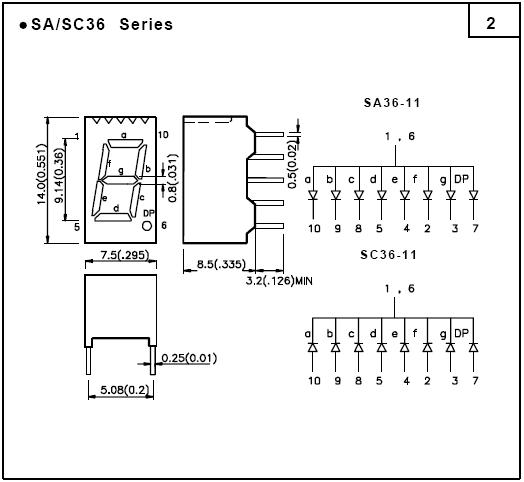
The selected LED display details:
Kingbright SA36-11SRWA
Red 9mm display
Common anode
Brightness 2200-9000 uCd @ 10mA
Conrad order code: 158780
Dimensions:
The Fluke 8050A display board circuit (photo)
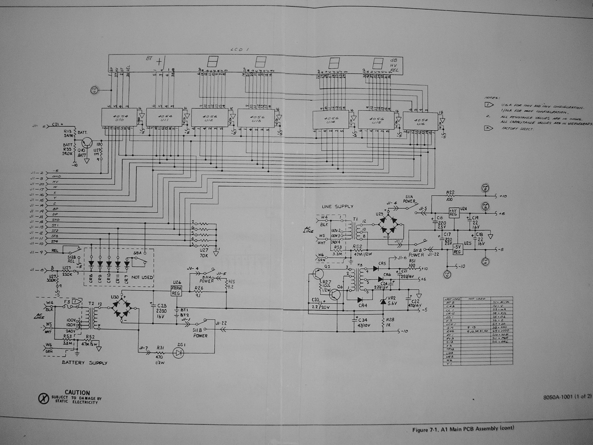
Circuit modifications:
Note
that each individual segment has a 2k2 resistor between it and the
driver pins. I soldered the cut resistors directly to each driver IC
and wired them from there to each segment. This was a bit more work
then I expected... The symbol LEDs have 1k in series. For a Fluke
with the battery option you would need an additional LED.
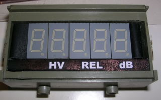
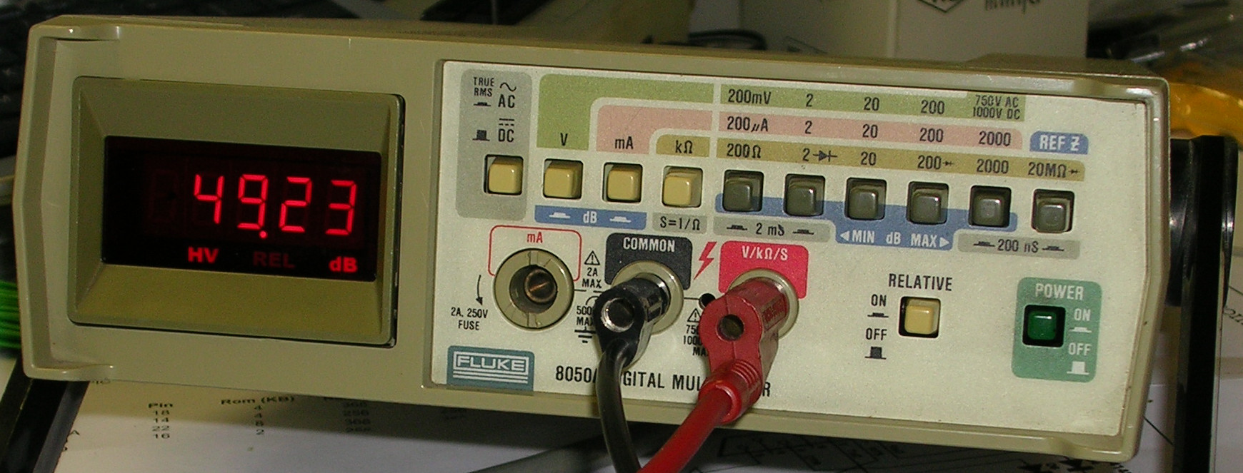
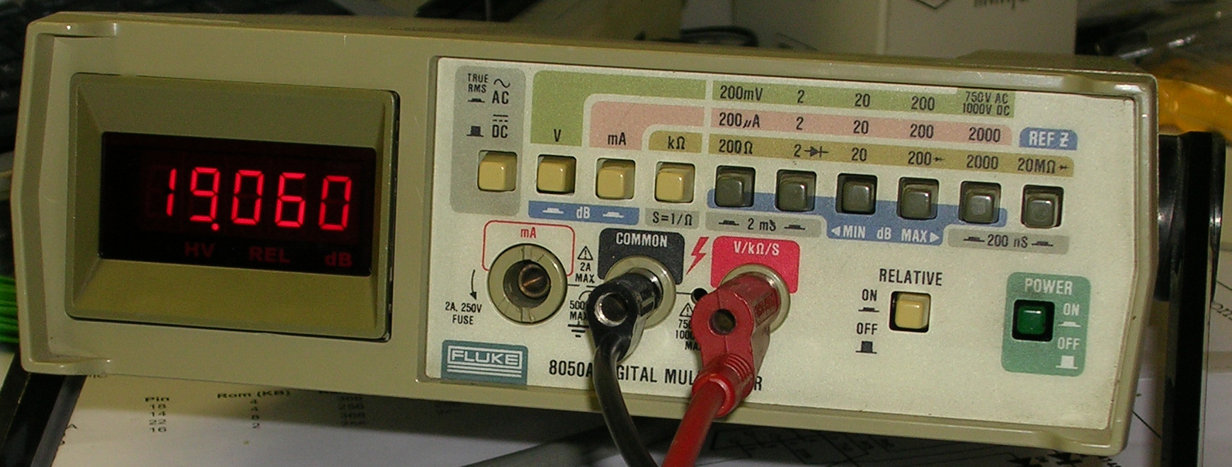
The results:
Further ideas RS-232 interace:
Now I understand the circuit en have seen the signals on an oscilloscope, I was thinking of making an isolated RS-232 interface to this meter. It is a desktop model that is mains powered, so keeping it switched is not a problem. This would allow long duration measurements like rechargable battery charge/discharge curves etcetera. To isolate the circuit to be measured from the computer would also require an opto isolated interface. It might never happen, but if it does I will update this page.
Last updated 4-september-2005.